RECOVERY SYSTEM FOR POLYOLEFIN SYNTHESIS CROSS-REFERENCE TO RELATED APPLICATION [0001] This application claims the benefit of U.S. Provisional Application number

System for Polyolefin Synthesis”, the entirety of which is incorporated by reference herein. FIELD OF INVENTION [0002] The present disclosure relates to polyolefin synthesis. BACKGROUND [0003] Polyolefin syntheses often include a monomer and a comonomer where the comonomer has a higher carbon-number than the monomer. For example, a polyethylene may be synthesized using ethylene monomer, 1-hexene comonomer, and a catalyst. The comonomer is typically high purity (e.g., 99%) and includes impurities that are primarily inert isomers (in the prescribed reaction) and saturates of the comonomer (e.g., 2-cis-hexene and hexane, respectively). [0004] In a polyolefin synthesis after polymerization, for example in a gas-phase fluidized bed reactor, the product stream is separated into a polymer stream and an unreacted components stream. The polymer stream can have impurities that are adhered to the products, such as hydrocarbons originating from unreacted monomers, unreacted comonomers, or other impurities, e.g., inert isomers and/or saturates of the comonomer. Generally, the hydrocarbons are stripped from the products using an inert gas, e.g., nitrogen, coupled with one or more separating and/or recovery techniques, e.g., condensers, membranes, or columns. Once stripped from the products, the hydrocarbons may be recovered and recycled for future polymerizations or directed to a flare where separation did not occur. [0005] Unfortunately, nitrogen imposes a severe thermodynamic limitation on the extraction of one or more hydrocarbons from the products, leading to an undesirably larger number of hydrocarbon impurities being sent to the flare, which equates to costly losses and undesirable emissions into the atmosphere. Hydrocarbon impurities of this type are described in, for example, U.S. Patent Publication No. 2020/0255564 A1. Additionally, nitrogen will often reduce the efficiency of the polymerization reaction as nitrogen provides less heat transfer in the polymerization reactor compared to other inert gases, due to nitrogen’s lower heat capacity and lower gas density. Previous attempts to reduce the use of nitrogen have focused on cleaning the reactor with alternative inert gases, as described in, for example, Chinese Patent Application No.: CN106467597B.
[0006] Other references of potential interest in this regard include: JP H-05-329317; US 5,199,962; US 5,089,033; US 2018/0162962; US2013/0291720; WO2022/187791; WO 2023/091854; as well as PCT application No. PCT/US2023/082941. [0007] There remains a need for improved polyolefin syntheses systems capable of reducing the amount of material flared (and/or reducing or eliminating undesirable flare emissions) as well as improved polymerization efficiencies. SUMMARY OF INVENTION [0008] The present disclosure provides various systems and methods. One method in accordance with various embodiments of the present disclosure includes recovering a polyolefin including one or more unreacted components from a polymerization reactor. The method includes contacting the polyolefin product with a purge gas to remove at least a portion of the unreacted components to produce (1) a polymer product having a reduced concentration of unreacted components and (2) a purge gas vent stream enriched in unreacted components. The purge gas comprises one or more of the following gases: hydrogen, methane, ethane, and ethylene; optionally in certain embodiments a portion of the purge gas can also comprise nitrogen, argon, and/or helium, but in other embodiments such gases are absent or substantially absent (e.g., at 100 ppm or less, such as 10 ppm or less). The method includes directing the purge gas vent stream to a purge gas recovery unit. The purge gas recovery unit is configured to cool the purge gas vent stream via a cooler to produce a cooled purge gas vent stream, compress the cooled purged gas vent stream to a pressure of about 60 psi to about 500 psi to form a compressed purge gas vent stream, cool the compressed purge gas vent stream to a temperature of about -30 °C to about 100 °C to form a cooled compressed purge gas vent stream, separate the cooled compressed purge gas vent stream into a gas product and a condensed product, extract the condensed product; and recycle at least a portion of the gas product to be introduced with the purge gas. [0009] The present disclosure also provides a process for recovering unreacted components from a polyolefin purge gas product. The process includes supplying a polymer product of a polymerization reactor to a purge bin. The polymer product includes one or more unreacted components. The purge bin includes a first region, a second region, a third region, and a fourth region. The process includes performing a first strip of the one or more unreacted components from the polymer product by contacting the polymer product in the first region with a first purge gas and recovering at least a portion of the first purge gas as a purge gas vent stream. The process includes performing a second strip of the one or more unreacted components from the polymer product by contacting the polymer product in the second region with a second
purge gas and directing the second purge gas to flare or a first flare gas recovery unit. The process includes performing a third strip of the one or more unreacted components from the polymer product by contacting the polymer product in the third region with a third purge gas to form a stripped polymer product and directing the third purge gas to flare or a second flare gas recovery unit. The process includes directing the stripped polymer product through the fourth region to a rotary feeder to recover the stripped polymer product. BRIEF DESCRIPTION OF THE DRAWINGS [0010] The following figures are included to illustrate certain aspects of the embodiments and should not be viewed as exclusive embodiments. The subject matter disclosed is capable of considerable modifications, alterations, combinations, and equivalents in form and function, as will occur to those skilled in the art and having the benefit of this disclosure. [0011] FIG. 1 depicts a schematic of an illustrative gas phase polymerization system for making polymers according to embodiments of the present disclosure. [0012] FIG.2 depicts a schematic of an illustrative recovery unit according to embodiments of the present disclosure. [0013] FIG.3 depicts a schematic of an illustrative purge bin according to embodiments of the present disclosure. [0014] While the disclosed process and system are susceptible to various modifications and alternative forms, the drawing illustrates a specific embodiment herein described in detail by way of example. It should be understood, however, that the description herein of a specific embodiment is not intended to limit the present disclosure to the particular forms disclosed, but on the contrary, the intention is to cover all modifications, equivalents, and alternatives falling within the spirit and scope of the present disclosure as defined by the appended claims. DETAILED DESCRIPTION [0015] The present disclosure provides improved polyolefin syntheses utilizing improved recovery systems for hydrocarbons, reducing the amount of greenhouse gas emissions from polymerizations, such as gas-phase polymerizations. The recovery systems provided can utilize a purge gas having a higher heat capacity and/or gas density value such as ethane or ethylene, as compared to nitrogen, to increase the efficiency and production rate of polyolefin products. Since the rate of heat generation during polymerization is directly related to the rate of polyolefin product formation, e.g., due to the polymerization being exothermic, increasing the heat capacity and the gas density of the cycle gas will lead to a larger production rate. Ethane and/or ethylene, having a higher heat capacity and/or gas density value than nitrogen, assists in producing a higher temperature at an outlet of a reactor chamber, which can cause a greater
temperature difference between the temperature of the gas exiting the reactor compared to the gas entering the reactor. Accordingly, by utilizing ethane and/or ethylene purge gas instead of nitrogen purge gas, the efficiency and production rate of the products will be improved due to the reaction being exothermic. [0016] The present disclosure also provides methods of enhanced hydrocarbon separations downstream of the reactor by using ethane gas as opposed to using nitrogen gas as a purge gas, where separations occur by stripping hydrocarbons from the polymer product to recover one or more hydrocarbons. Hydrocarbon separation in ethane avoids the need for costly separation techniques such as cryogenic distillation, pressure swing adsorption, or membrane technology which can reduce processing costs during gas-phase polymerization reactions. Due to the boiling point of ethane, distillation or condensers may be employed, limiting the need for costly separation techniques that nitrogen separation techniques require. Accordingly, hydrocarbons may be more efficiently extracted and recycled rather instead of being sent to flare, reducing the amount of greenhouse gas emissions from gas-phase polymerization reactions. [0017] The present disclosure also provides methods utilizing a recovery stream from a bin of a gas-phase polymerization reaction system where the recovery stream has a low nitrogen content, e.g., about 1% v/v to about 10% v/v. The recovery stream may either be introduced to a reactor of the gas-phase polymerization reaction system or may be sent to flare. By having a low nitrogen content, the recovery fluid stream can be reprocessed in an olefins processing plant, e.g., a plant to form olefins or react one or more olefins to form a polymer, to extract any residual or remaining hydrocarbons present in the recovery stream. Additionally, a reduction of nitrogen and increase of ethane and/or ethylene promotes efficient fuel combustion for any remaining residual gas sent to flare due to the ethane and/or ethylene having a higher heating value, which increases its combustion efficiency and lowers the undesirable emission of gases such as NO
x species. Also, or instead, the use of ethylene can be beneficial since it can be recycled (e.g., to polymerization reaction) and consumed, as opposed to a gas like nitrogen which will continue to accumulate in the system (and therefore ultimately require flaring or risk being discharged to atmosphere). [0018] The present disclosure also provides methods of employing heat integration with a purge gas such that the purge gas may match the temperature for nitrogen in the purge bin, purge gas line, or recovery unit. Heat integration may be performed using one or more heat exchangers, which may, in the case of gas-phase polymerizations, either cool the compressed gas of the recovery unit and/or heat the makeup gas of the recovery unit. The use of heat integration with the purge gas, such as ethane and/or ethylene, allows for reactions to be
performed to concurrently heat the makeup gas being recirculated in the recovery unit and cool the compressed gas exiting a compressor of the recovery unit. [0019] The present disclosure also provides methods utilizing a reduction of the use of nitrogen even where nitrogen is typically required to provide a barrier vapor lock to prevent hydrocarbon leak to the atmosphere. By substituting nitrogen with a hydrogen gas in a second purge section of a purge bin, nitrogen volume being sent to flare is reduced. By reducing the nitrogen volume, undesirable production of gases such as NOx from flare is reduced. Moreover, due to the substitution of nitrogen with hydrogen, reduced hydrocarbons are sent to flare as hydrogen gas is substantially free of hydrocarbons, and, unlike nitrogen, can readily be combusted without addition of supplemental carbon-containing gases such as hydrocarbon gases (which in turn increase undesired production and emission of CO and/or CO2). [0020] The present disclosure also provides methods of using a mixture of one or more of ethane, ethylene, or nitrogen with hydrogen and/or water vapor in the purge bin as a stripping gas to neutralize one or more catalytic components of the polymer product from continuing to undergo polymerization reactions in the purge bin. Additionally, the use of the mixture of one or more of ethane, ethylene, or nitrogen with hydrogen reduces the amount of greenhouse gases as hydrogen, when sent to flare downstream, combusts to form water vapor. [0021] Illustrative embodiments of the subject matter claimed below will now be disclosed. In the interest of clarity, some features of some actual implementations may not be described in this specification. It will be appreciated that in the development of any such actual embodiments, numerous implementation-specific decisions must be made to achieve the developer’s specific goals, such as compliance with system-related and business-related constraints, which will vary from one implementation to another. Moreover, it will be appreciated that such a development effort, even if complex and time-consuming, would be a routine undertaking for those of ordinary skill in the art having the benefit of this disclosure. [0022] The words and phrases used herein should be understood and interpreted to have a meaning consistent with the understanding of those words and phrases by those skilled in the relevant art. No special definition of a term or phrase, e.g., a definition that is different from the ordinary and customary meaning as understood by those skilled in the art, is intended to be implied by consistent usage of the term or phrase herein. [0023] The following discussion contains a non-exhaustive list of definitions of several specific terms used in this disclosure (other terms may be defined or clarified in a definitional manner elsewhere herein). These definitions are intended to clarify the meanings of the terms
used herein. It is believed that the terms are used in a manner consistent with their ordinary meaning, but the definitions are nonetheless elaborated on here for clarity. Definitions [0024] “Inert gas,” as used herein, refers to a gas that does not readily undergo chemical reactions with one or more of the reactants, monomers, comonomers, catalysts, or other chemical substance in a gas-phase polymerization reactor. [0025] “Carrier gas,” as used herein refers to a gas that carries at least a nominal amount of a first component, e.g., unreacted components, to a gas-phase polymerization reactor. In at least an embodiment the carrier gas is an inert gas. In at least an embodiment the carrier gas is a gas capable of reacting with non-polymer component(s) and/or polymer component(s). [0026] An “olefin,” alternatively referred to as “alkene,” is a linear, branched, or cyclic compound of carbon and hydrogen having at least one double bond. For purposes of this specification and the claims appended thereto, when a polymer or copolymer is referred to as comprising an olefin, the olefin present in such polymer or copolymer is the polymerized form of the olefin. For example, when a copolymer is said to have an "ethylene" content of 35 wt% to 55 wt%, it is understood that the mer unit in the copolymer is derived from ethylene in the polymerization reaction and said derived units are present at 35 wt% to 55 wt%, based upon the weight of the copolymer. A “polymer” has two or more of the same or different mer units. A “homopolymer” is a polymer having mer units that are the same. A “copolymer” is a polymer having two or more mer units that are different from each other. A “terpolymer” is a polymer having three mer units that are different from each other. Accordingly, the definition of copolymer, as used herein, includes terpolymers and the like. “Different” as used to refer to mer units indicates that the mer units differ from each other by at least one atom or are different isomerically. An "ethylene polymer" or "ethylene copolymer" is a polymer or copolymer comprising at least 50 mol% ethylene derived units, a "propylene polymer" or "propylene copolymer" is a polymer or copolymer comprising at least 50 mol% propylene derived units, and so on. [0027] -olefin. [0028] Unless otherwise specified, the term “C
n” means hydrocarbon(s) having n carbon atom(s) per molecule, wherein n is a positive integer. [0029] The term “hydrocarbon” means a class of compounds containing hydrogen bound to carbon, and encompasses (i) saturated hydrocarbon compounds, (ii) unsaturated hydrocarbon compounds, and (iii) mixtures of hydrocarbon compounds (saturated and/or unsaturated), including mixtures of hydrocarbon compounds having different values of n.
Likewise, a “Cm-Cy” group or compound refers to a group or compound comprising carbon atoms at a total number thereof in the range from m to y. Thus, a C
1-C
50 alkyl group refers to an alkyl group comprising carbon atoms at a total number thereof in the range from 1 to 50. [0030] “Catalyst,” as used in the method disclosed herein, is the same catalyst throughout the method. That is to say, that the catalyst used for making the first polyethylene will be the same catalyst used for making the second polyethylene, and inherently any transitional polyethylene produced using the gas-phase polymerization process. [0031] “C
n” as used herein, and unless otherwise specified, the term means hydrocarbon(s) having n carbon atom(s) per molecule, wherein n is a positive integer. [0032] “Induced condensing agent (ICA),” as used herein, means one or more inert condensable fluids which are readily volatile liquid hydrocarbons, which may be selected from saturated hydrocarbons containing from 2 to 10 carbon atoms, such as 3 to 10 carbon atoms. Some suitable saturated hydrocarbons are propane, n-butane, isobutane, n-pentane, isopentane, neopentane, n-hexane, isohexane, and other saturated C6 hydrocarbons, n-heptane, n-octane and other saturated C7 and C8 hydrocarbons or mixtures thereof. A class of exemplary inert condensable hydrocarbons are C5 and C6 saturated hydrocarbons. Another class of exemplary hydrocarbons are C
4 to C
6 saturated hydrocarbons. Exemplary hydrocarbons for use as condensable fluids include pentanes, such as isopentane. The condensable fluids may also include polymerizable condensable comonomers such as olefins, diolefins or mixtures thereof including some of the monomers mentioned herein which may be partially or entirely incorporated in the polymer product. [0033] “Efficiency,” as used herein, refers to the amount of actual polymer product that is produced as a result of the gas-phase polymerization reaction compared to the amount of unreacted components, e.g., unreacted monomers and unreacted comonomers that remain in the product after polymerization. Efficiency may be represented by a w/v % of the total product formed. For example, a polymerization may have an efficiency of 90% where the reactants polymerized to produce 90 w/v% product and 10 w/v% of unreacted components. [0034] “Production rate,” as used herein, refers to the amount of polymer product produced per unit time based on the amount of reactant that is introduced into the polymerization reactor, where the unit time may be represented by seconds, minutes, hours, days, or the like. [0035] “Polyethylene,” as used herein, means an ethylene homopolymer or a copolymer comprising at least 89 wt.% ethylene. The terms “polyethylene polymer,” “polyethylene,” “ethylene polymer,” “ethylene copolymer,” and “ethylene-based polymer” have the same meaning as polyethylene copolymer, except where otherwise indicated (e.g., where a
polyethylene homopolymer is referred to, this means a polymer formed from ethylene monomer without comonomer units, e.g., 100 wt% ethylene-derived units). [0036] “Polymerization conditions,” as used herein, means conditions conducive to the reaction of one or more olefin monomers when contacted with an activated olefin polymerization catalyst to produce a polyolefin polymer, including a skilled artisan’s selection of temperature, pressure, reactant concentrations, optional solvent/diluents, reactant mixing/addition parameters, and other conditions within at least one polymerization reactor. [0037] “Reactor system,” as used herein, means the reactor and piping and equipment containing the circulating loop of cycle fluid, including, but not limited to, the cycle fluid heat exchanger. [0038] “Recovery efficiency,” as used herein, refers to the amount of unreacted components, e.g., unreacted monomers and unreacted comonomers, that are recovered from the polymer product after polymerization. Recovery efficiency may be represented by a % v/v based on the volume of the unreacted components compared to the volume of the polymer product. Polymerization Process [0039] The present disclosure provides methods for recovering hydrocarbons. During normal operations, a gas phase polymerization process comprises continuous addition of a catalyst, ethylene monomer, and optionally one or more comonomers and/or hydrogen, to a fluidized bed in a polymerization reaction zone under a set of polymerization conditions and withdrawing a polyethylene having a density and melt index (I2). [0040] FIG. 1 depicts a flow diagram of an illustrative gas phase polymerization system 100 for making polymers, according to one or more embodiments. The polymerization system 100 can include a reactor 101 in fluid communication with one or more discharge tanks 155 (only one shown), compressors 170 (only one shown), heat exchangers 175 (only one shown), purge bins 180 (only one shown), and purge gas recovery units 182 (only one shown). The polymerization system 100 can also include more than one reactor 101 arranged in series, parallel, or configured independent from the other reactors, each reactor having its own associated discharge tanks 155, compressors 170, heat exchangers 175, purge bins 180, or purge gas recovery units 182 or alternatively, sharing any one or more of the associated discharge tanks 155, compressors 170, heat exchangers 175, purge bins 180, or purge gas recovery units 182. For simplicity and ease of description, the polymerization system 100 will be further described in the context of a single reactor train.
[0041] The reactor 101 can include a cylindrical section 103, a transition section 105, and a velocity reduction zone or dome 107. The cylindrical section 103 is disposed adjacent the transition section 105. The transition section 105 can expand from a first diameter that corresponds to the diameter of the cylindrical section 103 to a larger diameter adjacent the dome 107. As mentioned above, the location or junction at which the cylindrical section 103 connects to the transition section 105 is referred to as the “neck” or the “reactor neck” 104. The dome 107 has a bulbous shape. One or more cycle fluid lines 115 and vent lines 118 can be in fluid communication with the top head 107. The reactor 101 can include the fluidized bed 112 in fluid communication with the top head 107. [0042] In general, the height to diameter ratio of the cylindrical section 103 can vary in the range of from about 2:1 to about 5:1. The range, of course, can vary to larger or smaller ratios and depends, at least in part, upon the desired production capacity and/or reactor dimensions. The cross-sectional area of the dome 107 is typically within the range of from about 2 to about 3 multiplied by the cross-sectional area of the cylindrical section 103. [0043] The velocity reduction zone or dome 107 has a larger inner diameter than the fluidized bed 112. As the name suggests, the velocity reduction zone 107 slows the velocity of the gas due to the increased cross-sectional area. This reduction in gas velocity allows particles entrained in the upward moving gas to fall back into the bed, allowing primarily only gas to exit overhead of the reactor 101 through the cycle fluid line 115. The cycle fluid recovered via line 115 can contain less than about 10 wt%, less than about 8 wt%, less than about 5 wt%, less than about 4 wt%, less than about 3 wt%, less than about 2 wt%, less than about 1 wt%, less than about 0.5 wt%, or less than about 0.2 wt% of the particles entrained in fluidized bed 112 of the particles entrained in fluidized bed 312 over a period of time, e.g. about less than 10 wt% in mass per unit time. [0044] The reactor feed via line 110 can be introduced to the polymerization system 100 at any point. For example, the reactor feed via line 110 can be introduced to the cylindrical section 103, the transition section 105, the velocity reduction zone 107, to any point within the cycle fluid line 115, or any combination thereof. Figure 1 depicts the reactor feed via line 110 entering the cycle fluid in line 115 after the heat exchanger 175, however the reactor feed via line 110 may be implemented in one or more alternative locations, e.g., before the heat exchange 175 or after the heat exchanger 175. The catalyst feed via line 113 can be introduced to the polymerization system 100 at any point. For example, the catalyst feed via line 113 is introduced to the fluidized bed 112 within the cylindrical section 103. Additional feed lines (e.g., lines 130 and/or 133 as shown in FIG.1) can be utilized and located at any of the points
just mentioned with respect to feed line 110; any one or more of these feed lines can be used to convey monomer(s), ICA(s), inert carrier gases such as nitrogen, or the like to the cycle gas flowing through the system. [0045] During normal operation, e.g., polymer production, under a given set of operating conditions the fluidized bed may be maintained at essentially a constant height by withdrawing a portion of the bed as polymer product at the rate of formation of the particulate polymer product. Since the rate of heat generation during polymerization is directly related to the rate of product formation, a temperature rise of the fluid across the reactor (the difference in temperature between reactor feed line 110 and exit cycle fluid via line 115) is indicative of the rate of particulate polymer formation at a constant fluid velocity if no or negligible vaporizable liquid is present in the inlet fluid. The temperature rise of the fluid across the reactor, e.g., the temperature of the cycle gas exiting the reactor minus the temperature of the cycle gas reactor during polymer production can range from a low of about 5°C, about 10°C, or about 15°C to a high of about 40°C, about 50°C, or about 55°C. Accordingly, and without being bound by theory, a cycle gas that has a higher heat capacity and/or gas density value, allows for a larger DT, which increases both the reaction efficiency and the production rate of an exothermic gas-phase polymerization reaction of the present disclosure. [0046] The reactor feed line 110 feeds one or more unreacted monomers or unreacted comonomers in a cycle gas stream. The cycle gas stream may include a cycle gas having a heat capacity , e.g., greater than 130 J/molK, to ensure that the DT is maintained, which will assist in producing a higher rate of particular polymer formation. For example, the cycle gas stream that carries the one or more unreacted monomers or unreacted comonomers through the reactor feed line 110 can include ethane, ethylene, methane, or the like. For example, a cycle gas may include an ethane gas in an amount of about 95% v/v ethane to about 100 % v/v ethane, such as about 95% v/v, about 96% v/v, about 97% v/v, about 97% v/v, about 99% v/v, or about 100% v/v, low impurities, e.g., about 0.0% v/v to about 10% v/v, such as about 0.01% v/v, about 0.1% v/v, about 1% v/v, about 2% v/v, about 4% v/v, about 6% v/v, about 8% v/v, or about 10% v/v, a low olefinic content, e.g., about 0.0% v/v to about 10% v/v, such as about 0.01% v/v, about 0.1% v/v, about 1% v/v, about 2% v/v, about 4% v/v, about 6% v/v, about 8% v/v, or about 10% v/v. In an embodiment, the cycle gas including ethane gas may have a low temperature, e.g., about 40 °F to about 120 °F, such as about 60 °F to about 100 °F, 80 °F to about 90 °F, or about 40 °F to about 100 °F. In an embodiment, the cycle gas including ethylene gas may have a low temperature, e.g., about -10 °F to about 40 °F, such as about -10
°F to about 10 °F, 10 °F to about 30 °F, or about 20 °F to about 40 °F. Without being bound by theory, a higher heat capacity and/or gas density value will cause a greater temperature difference between the temperature of the gas exiting the reactor compared to the gas entering the reactor due to the larger amount of energy that is expelled in the reaction, which increases the reaction efficiency and the production rate. [0047] The cycle fluid via line 115 can be compressed in the compressor 170 and then passed through the heat exchanger 175 where heat can be exchanged between the cycle fluid and a heat transfer medium. For example, during normal operating conditions a cool or cold heat transfer medium via line 171 can be introduced to the heat exchanger 175 where heat can be transferred from the cycle fluid in line 115 to produce a heated heat transfer medium via line 177 and a cooled cycle fluid via line 115. In another example, during idling of the reactor 101 a warm or hot heat transfer medium via line 171 can be introduced to the heat exchanger 175 where heat can be transferred from the heat transfer medium to the cycle fluid in line 115 to produce a cooled heat transfer medium via line 177 and a heated cycle fluid via line 115. The terms “cool heat transfer medium” and “cold heat transfer medium” refer to a heat transfer medium having a temperature less than the fluidized bed 112 within the reactor 101. The terms “warm heat transfer medium” and “hot heat transfer medium” refer to a heat transfer medium having a temperature greater than the fluidized bed 112 within the reactor 101. The heat exchanger 175 can be used to cool the fluidized bed 112 or heat the fluidized bed 112 depending on the particular operating conditions of the polymerization system 100, e.g., reactor start-up, normal operation, idling, and shut down. For example, the heat exchanger 175 can cool the cycle fluid in line 115 to about 100 °C to about 250 °C or lower. Alternatively, the heat exchanger 175 can heat the cycle fluid in line 115 to about 50 °C to about 500 °C , e.g., about 50 °C to about 100 °C, about 100 °C to about 300 °C, or about 300 °C to about 500 °C. Illustrative heat transfer mediums can include, but are not limited to, water, air, glycols, or the like. It is also possible to locate the compressor 170 downstream from the heat exchanger 175 or at an intermediate point between several heat exchangers 175. [0048] After cooling, all or a portion of the cycle fluid via line 115 can be returned to the reactor 101. The cooled cycle fluid in line 115 can absorb the heat of reaction generated by the polymerization reaction. The heat transfer medium in line 171 can be used to transfer heat to the cycle fluid in line 115 thereby introducing heat to the polymerization system 100 rather than removing heat therefrom. The heat exchanger 175 can be of any type of heat exchanger. Illustrative heat exchangers can include, but are not limited to, shell and tube, U-tube, and the like. For example, the heat exchanger 175 can be a shell and tube heat exchanger where the
cycle fluid via line 115 can be introduced to the tube side and the heat transfer medium can be introduced to the shell side of the heat exchanger 175. If desired, several heat exchangers can be employed, in series, parallel, or a combination of series and parallel, to lower or increase the temperature of the cycle fluid in stages. [0049] In some embodiments, the cycle gas via line 115 is returned to the reactor 101 and to the fluidized bed 112 through fluid distributor plate (“plate”) 119. The plate 119 can be installed at the inlet to the reactor 101 to prevent polymer particles from settling out and agglomerating into a solid mass and to prevent liquid accumulation at the bottom of the reactor 101 as well to facilitate easy transitions between processes which contain liquid in the cycle stream 115 and those which do not and vice versa. Although not shown, the cycle gas via line 115 can be introduced into the reactor 101 through a deflector disposed or located intermediate an end of the reactor 101 and the distributor plate 119. [0050] The catalyst feed via line 113 can be introduced to the fluidized bed 112 within the reactor 101 through one or more injection nozzles (not shown) in fluid communication with line 113. The catalyst feed is introduced as pre-formed particles in one or more liquid or gas carriers (e.g., a catalyst slurry or a particle in a gas). Suitable liquid carriers can include mineral oil and/or liquid or gaseous hydrocarbons including, but not limited to, propane, butane, isopentane, hexane, heptane octane, or mixtures thereof. Suitable gas carriers include carrier gases that have a higher heat capacity and/or gas density value, e.g., ethane, ethylene, or a combination thereof, to provide a higher temperature during the polymerization reaction, which increases the temperature at the velocity reduction zone or dome 107 and drives the reaction to produce more products at a higher efficiency. For example, the gas carrier of line 113 may include about 20% ethylene to about 100% ethylene, e.g., about 20% v/v to about 40% v/v, about 30% v/v to about 50% v/v, about 40% v/v to about 60% v/v, about 50% v/v to about 70% v/v, about 60% v/v to about 80% v/v, about 70% v/v to about 90% v/v, or about 80% v/v to about 100% v/v. As a further example, the gas carrier of line 113 may include about 0% ethane to about 100% ethane, e.g., about 0% v/v to about 20% v/v, about 10% v/v to about 30% v/v, about 20% v/v to about 40% v/v, about 30% v/v to about 50% v/v, about 40% v/v to about 60% v/v, about 50% v/v to about 70% v/v, about 60% v/v to about 80% v/v, about 70% v/v to about 90% v/v, or about 80% v/v to about 100% v/v. Without being bound by theory, a gas carrier of line 113 being ethylene may be advantageous as there is no buildup of gases that do not participate in the gas-phase polymerization reaction. Without being bound by theory, a carrier gas of ethane or ethylene, having a higher heat capacity and/or gas density value will enable
the removal of additional heat in the cycle gas cooler, which will assist in driving the reaction forward to increase the production rate of polymer product. [0051] Alternatively, the carrier gas could potentially be vaporized (gaseous) isobutane. If isobutane is used in this manner, it would preferably be separated (e.g., in the downstream recovery unit 182), and preferably sent to a separate process (for instance, potentially an olefins production process upstream of the polymerization reaction system) to avoid potential accumulation of this non-reaction-participating substance in the system. If not separated and/or removed from the system in this manner, then the isobutane in the system could require flaring for inert control. If handled appropriately downstream (e.g., as just discussed), this substitution versus nitrogen could further improve cycle gas density and heat capacity, allowing for increased production rate of polymer product. [0052] The gas carrier can also be used to carry the catalyst slurry into the reactor. In one example, the catalyst can be a dry powder. In another example, the catalyst can be dissolved in a liquid carrier and introduced to the reactor 101 as a solution. The catalyst via line 113 can be introduced to the reactor 101 at a rate sufficient to maintain polymerization of the monomer(s) therein. Hydrogen can be added via line 114. [0053] Fluid via line 161 can be separated from a polymer product recovered via line 117 from the reactor 101. The fluid can include unreacted monomer(s), hydrogen, induced condensing agents (ICAs), and/or inerts such as ethane and/or ethylene. The separation of the fluid can be accomplished when fluid and/or product leave the reactor 101 and enter the product discharge tank 155 (one is shown) through valve 157, which can be, for example, a ball valve designed to have minimum restriction to flow when opened. Positioned above and below the product discharge tank 155 can be conventional valves 159, 167. The valve 167 allows passage of product therethrough. For example, to discharge the polymer product from the reactor 101, valve 157 can be opened while valves 159, 167 are in a closed position. Product and fluid enter the product discharge tank 155. Valve 157 is closed and the product is allowed to settle in the product discharge tank 155. Valve 159 is then opened permitting fluid to flow via line 161 from the product discharge tank 155 to the reactor 101. Valve 159 can then be closed and valve 167 can be opened and any product in the product discharge tank 155 can flow into and be recovered via line 168. Valve 167 can then be closed. The particular timing sequence of the valves 157, 159, and 167 can be accomplished by use of conventional programmable controllers which are well known in the art. The processed fluid can be introduced to the reactor 101. Alternatively, the processed fluid can be introduced to the recycle line 115 (not shown).
[0054] The product via line 168 can be introduced to a purge bin 180 (only one is shown). Alternatively, the product line 168 can be introduced to a plurality of separation units, in series, parallel, or a combination of series and parallel, to further separate gases and/or liquids from the product. The purge bin 180 may receive the product via line 168, in which a plurality of gas stripping streams within the purge bin 180 may direct one or more purge vent streams via line 184 to a purge gas recovery unit 182, as described below with reference to FIG. 3. Additionally, the purge bin 180 may receive the product via line 168 and recover one or more polymer products, via exit line 198, as described below with reference to FIG.3. Additionally, the purge bin 180 may direct one or more purge gases, e.g., hydrogen, to a hydrogen recovery plant, such as a blue hydrogen plant, via line 309 and/or 318, as described below with reference to FIG.3. Without being bound by theory, the gas stripping streams may include one or more stripping gases such as nitrogen, argon, helium, ethane, methane, or ethylene; alternately any one or more of the gas stripping streams can have substantially no nitrogen, argon, or helium (e.g., 100 ppm or less such as 10 ppm or less such as 0 ppm, on basis of either mass or volume, of nitrogen and/or argon), but may include any one or more of the other just-listed gases. For example, the stripping gas may include about 20% ethylene to about 100% ethylene, e.g., about 20% v/v to about 40% v/v, about 30% v/v to about 50% v/v, about 40% v/v to about 60% v/v, about 50% v/v to about 70% v/v, about 60% v/v to about 80% v/v, about 70% v/v to about 90% v/v, or about 80% v/v to about 100% v/v. As a further example, the stripping gas may include about 0% ethane to about 100% ethane, e.g., about 0% v/v to about 20% v/v, about 10% v/v to about 30% v/v, about 20% v/v to about 40% v/v, about 30% v/v to about 50% v/v, about 40% v/v to about 60% v/v, about 50% v/v to about 70% v/v, about 60% v/v to about 80% v/v, about 70% v/v to about 90% v/v, or about 80% v/v to about 100% v/v. In some embodiments, only one, two, or three, but not all, of the gas stripping streams can include nitrogen, argon, and/or helium. For instance, in an embodiment, the purge bin 180 can include a fourth region comprising a rotary feeder and a nitrogen gas inlet to prevent one or more hydrocarbons from leaking out of the purge bin, as described below in reference to FIG.3. [0055] The purge vent streams in line 184 can have a concentration of one or more unreacted monomers, unreacted comonomers, impurities, or catalytic components ranging of 500 ppmw or greater. In an embodiment, the purge vent stream in line 184 can be a purge gas that is about 500 ppmw or greater of hydrocarbons. In at least an embodiment, the purge vent stream in line 184 can include about 0 % v/v to about 100 % v/v of one or more unreacted monomers, unreacted comonomers, impurities, or catalytic components, e.g., about 0 % v/v to about 20 % v/v, about 20 % v/v to about 40 % v/v, about 40 % v/v to about 60 % v/v, about 60
% v/v to about 80 % v/v, or about 80 % v/v to about 100 % v/v. For example, the purge vent stream in line 184 can include about 32 % v/v to about 35 % v/v ethene, about 2 % v/v to about 4 % v/v ethane, about 20 % v/v to about 22 % v/v of C4 compounds (e.g., butane, 1-butene, 2- butene, 2methyl propane, etc.); about 12 % v/v to about 15 % v/v of C
5 compounds (e.g., pentane, 1-pentene, 2-pentene, isopentane (i.e., 2-methyl butane), etc.); about 18 % v/v to about 22 % v/v of C
6 compounds (e.g., 1-hexene, 2-hexene, hexane, isohexane (i.e., 2- methylpentane), etc.), or combinations thereof. In at least an embodiment, the purge vent stream in line 184 can include about 4 % v/v to about 6 % v/v of nitrogen. The fluid in line 184 may be processed in the purge gas recovery unit 182, as described below with reference to FIG.2. [0056] The purge gas recovery unit 182 may receive a makeup gas stream from a line 186 (instead of or in addition to a stream 202) to assist in cooling the fluid in line 184. In at least an embodiment, the makeup gas stream from line 186 may cool the fluid in line 208 at the interchanger 210, while concurrently heating the makeup gas stream from line 186, to allow for heated gas in line 188. Without being bound by theory, concurrent heating of the makeup gas stream in line 186, to produce a heated gas stream in line 188, and cooling of fluid in line 208 may provide an improved energy efficiency in purging as less supplemental heat is required to be used to warm the fluid in line 186 prior to being introduced to the purge bin 180 via line 196. The makeup gas stream may include one or more makeup gases capable of cooling the fluid in line 184. For example, the makeup stream may include a makeup gas such as argon, nitrogen, ethane, ethylene, or methane; alternately the makeup stream can have substantially no nitrogen or argon (e.g., 100 ppm or less such as 10 ppm or less such as 0 ppm, on basis of either mass or volume, of nitrogen and/or argon), but may include any one or more of the other just-listed gases. For example, the makeup gas may include about 20% ethylene to about 100% ethylene, e.g., about 20% v/v to about 40% v/v, about 30% v/v to about 50% v/v, about 40% v/v to about 60% v/v, about 50% v/v to about 70% v/v, about 60% v/v to about 80% v/v, about 70% v/v to about 90% v/v, or about 80% v/v to about 100% v/v. As a further example, the makeup gas may include about 0% ethane to about 100% ethane, e.g., about 0% v/v to about 20% v/v, about 10% v/v to about 30% v/v, about 20% v/v to about 40% v/v, about 30% v/v to about 50% v/v, about 40% v/v to about 60% v/v, about 50% v/v to about 70% v/v, about 60% v/v to about 80% v/v, about 70% v/v to about 90% v/v, or about 80% v/v to about 100% v/v. The makeup gas stream may be introduced in the recovery unit 180 at a lower pressure than the pressure of line 184, such that the drop in pressure results in a further chilling of the fluid in line 184.
[0057] A recovery fluid in line 188 may leave the purge gas recovery unit 182, in which the recovery fluid may be introduced to the reactor 101 via line 190 or may be introduced back to the purge bin via line 196. Alternatively, the recovery fluid 188 may be introduced to the recycle line 115 (not shown). The recovery fluid in line 188 may be regulated by one or more valves 190. The one or more valves 190 may limit or restrict a flow of the recovery fluid in line 188 from being introduced to the reactor 101 or the recycle line 115 (not shown). [0058] The recovery fluid in line 188 may be diverted through an exhaust valve 192. The exhaust valve 192 may open or close an exhaust line 194. The exhaust line 194 may transmit fluid to flare. Alternatively, the exhaust line 194 may be transferred to an olefins processing plant to perform one or more hydrocarbon recovery processes. In an embodiment, the recovery fluid in line 194 may have a low nitrogen content, e.g., about 1% v/v to about 10% v/v, e.g., about 1% v/v to about 3% v/v, about 2% v/v to about 4% v/v, about 5% v/v to about 7% v/v, about 6% v/v to about 8 % v/v, about 7% v/v to about 9 % v/v, or about 8% v/v to about 10% v/v. Without being bound by theory, the low nitrogen content within the recovery fluid line may allow for reprocessing in an olefins plant to extract the one or more remaining hydrocarbons of the recovery fluid. Additionally, increase of ethane promotes efficient fuel combustion for any residual gas that is sent to flare due to the ethane having a higher heating value than nitrogen, which increases its combustion efficiency. Moreover, a reduction of nitrogen reduces flaring of nitrogen, which reduces NO
x greenhouse gases from being emitted. [0059] The purged gas in the top of purge bin 180 prior to becoming stream 184 is typically passed through a filtering device (not shown) intended to ensure no solid particles leave in stream 184. This filtering device may be subjected to intermittent force (e.g., pulsed bursts of gas) intended to dislodge any solid particles adhered to the surface or internals of the device. One example of such a device is a pulse jet dust collector. This example device includes sock- like filter devices that can be blown back with gas, e.g., nitrogen, to limit accumulation of small particles on the face of the socks, which if allowed to build up will hinder filtration. In accordance with various embodiments herein, this blowback function can advantageously be carried out using gas drawn from downstream of the recovery compression system, e.g., from stream 188, instead of using fresh nitrogen. This is another means to limit the amount of inert gas added to the process and that otherwise would ultimately be flared. [0060] Similarly, the purge gases in stream 199 (or detailed more extensively as streams 318 and 309 later) exiting to the flare or recovery systems previously discussed can also run through a filtering device (e.g., a pulse jet dust collector) to prevent sending polymer product particles to the recovery systems. In this case, however, drawing gas from another portion of
the process would be undesirable insofar as gases in stream 199 are likely to be flared in many configurations; such gases would accordingly only add to hydrocarbon being flared (and therefore potentially contribute to undesirable flare byproducts such as CO and/or CO2). However, in this case, hydrogen gas is a particularly advantageous alternative for use as the blowback gas, since flaring hydrogen merely creates water vapor as a byproduct. [0061] One embodiment of a product discharge system which can be alternatively employed is that disclosed in U.S. Pat. No. 4,621,952. Such a system employs at least one (parallel) pair of tanks comprising a settling tank and a transfer tank arranged in series and having the separated gas phase returned from the top of the settling tank to a point in the reactor near the top of the fluidized bed. [0062] The reactor 101 can be equipped with one or more vent lines 118 to allow venting the reactor. The reactor 101 can be free from the use of stirring and/or wall scraping. The cycle line 115 and the elements therein (compressor 170, heat exchanger 175) can be smooth surfaced and devoid of unnecessary obstructions so as not to impede the flow of cycle fluid or entrained particles. [0063] The conditions for polymerizations vary depending upon the monomers, catalysts, catalyst systems, and equipment availability. The specific conditions are known or readily derivable by those skilled in the art. For example, the temperatures can be within the range of bout 140°C, often about 15°C to about 120°C, and more often about 70°C to about 110°C. Pressures can be within the range of from about 10 kPag to about 10,000 kPag, such as about 500 kPag to about 5,000 kPag, or about 1,000 kPag to about 2,200 kPag, for example. Catalyst Systems [0064] The term “catalyst system” includes at least one “catalyst component” and at least one “activator,” alternately at least one co-catalyst. The catalyst system can also include other components, such as supports, and is not limited to the catalyst component and/or activator alone or in combination. The catalyst system can include any number of catalyst components in any combination as described, as well as any activator in any combination as described. [0065] The term “catalyst component” or “catalyst compound” includes any compound that, once appropriately activated, is capable of catalyzing the polymerization or oligomerization of olefins. The catalyst component may include at least one Group 3 to Group 12 atom and optionally at least one leaving group bound thereto. The term “leaving group” refers to one or more chemical moieties bound to the metal center of the catalyst component that can be abstracted from the catalyst component by an activator, thereby producing the
species active towards olefin polymerization or oligomerization. Suitable activators are described in detail below. [0066] As used herein, in reference to Periodic Table “Groups” of Elements, the “new” numbering scheme for the Periodic Table Groups are used as in the CRC Handbook of Chemistry and Physics (David R. Lide, ed., CRC Press 81st ed.2000). [0067] Suitable metallocene catalyst compounds can include, but are not limited to, metallocenes described in U.S. Pat. Nos.: 7,179,876; 7,169,864; 7,157,531; 7,129,302; 6,995,109; 6,958,306; 6,884748; 6,689,847; 5,026,798; 5,703,187; 5,747,406; 6,069,213; 7,244,795; 7,579,415; U.S. Patent Application Publication No. 2007/0055028; and WO Publications WO 97/22635; WO 00/699/22; WO 01/30860; WO 01/30861; WO 02/46246; WO 02/50088; WO 04/022230; WO 04/026921; and WO 06/019494. [0068] As used herein, the terms “activator” refers to any compound or combination of compounds, supported or unsupported, which can activate a catalyst compound or component, such as by creating a cationic species of the catalyst component. For example, this can include the abstraction of at least one leaving group (the “X” group in the single site catalyst compounds described herein) from the metal center of the catalyst compound/component. Activators can include Lewis acids such as cyclic or oligomeric poly(hydrocarbylaluminum oxides) and so called non-coordinating activators (“NCA”) (alternately, “ionizing activators” or “stoichiometric activators”), or any other compound that can convert a neutral metallocene catalyst component to a metallocene cation that is active with respect to olefin polymerization. Illustrative Lewis acids include, but are not limited to, aluminoxane (e.g., methylaluminoxane “MAO”), modified aluminoxane (e.g., modified methylaluminoxane “MMAO” and/or tetraisobutyldialuminoxane “TIBAO”), and alkylaluminum compounds. Ionizing activators (neutral or ionic) such as tri (n-butyl)ammonium tetrakis(pentafluorophenyl)boron may be also be used. Further, a trisperfluorophenyl boron metalloid precursor may be used. Any of those activators/precursors can be used alone or in combination with the others. There are a variety of methods for preparing aluminoxane and modified aluminoxanes known in the art. [0069] The catalyst compositions can include a support material or carrier. As used herein, the terms “support” and “carrier” are used interchangeably and are any support material, including a porous support material, for example, talc, inorganic oxides, and inorganic chlorides. The catalyst component(s) and/or activator(s) can be deposited on, contacted with, vaporized with, bonded to, or incorporated within, adsorbed or absorbed in, or on, one or more supports or carriers. Other support materials can include resinous support materials such as polystyrene, functionalized or crosslinked organic supports, such as polystyrene divinyl
benzene polyolefins or polymeric compounds, zeolites, clays, or any other organic or inorganic support material and the like, or mixtures thereof. [0070] Inorganic oxides supports can include Group 2, 3, 4, 5, 13 or 14 metal oxides. Exemplary supports include silica, which may or may not be dehydrated, fumed silica, alumina, silica-alumina and mixtures thereof. Other useful supports include magnesia, titania, zirconia, magnesium chloride, montmorillonite, phyllosilicate, zeolites, talc, clays, and the like. Also, combinations of these support materials may be used, for example, silica-chromium, silica- alumina, silica-titania and the like. Additional support materials may include those porous acrylic polymers described in EP 0767184, which is incorporated herein by reference. [0071] The polymer product(s) produced in the reactor can be or include any type of polymer or polymeric material. For example, the polymer product can include homopolymers of olefins (e.g., homopolymers of ethylene), and/or copolymers, terpolymers, and the like of olefins, particularly ethylene, and at least one other olefin. Illustrative polymers can include, but are not limited to, polyolefins, polyamides, polyesters, polycarbonates, polysulfones, polyacetals, polylactones, acrylonitrile-butadiene-styrene polymers, polyphenylene oxide, polyphenylene sulfide, styrene-acrylonitrile polymers, styrene maleic anhydride, polyimides, aromatic polyketones, or mixtures of two or more of the above. Suitable polyolefins can include, but are not limited to, polymers comprising one or more linear, branched or cyclic C2 to C
40 olefins, such as polymers comprising propylene copolymerized with one or more C
3 to C40 olefins, such as a C3 to C20 alpha olefin, more such as C3 to C10 alpha-olefins. Exemplary polyolefins include, but are not limited to, polymers comprising ethylene including but not limited to ethylene copolymerized with a C3 to C40 olefin, such as a C3 to C20 alpha olefin, more such as propylene and or butene. Polymer Products [0072] Example polymers include homopolymers or copolymers of C2 to C40 olefins, such as C
2 to C
20 olefins, such as a copolymer of an alpha-olefin and another olefin or alpha-olefin (ethylene is defined to be an alpha-olefin for purposes of this disclosure). The polymers may be or include homo polyethylene, homo polypropylene, propylene copolymerized with ethylene and or butene, ethylene copolymerized with one or more of propylene, butene or hexene, and optional dienes. Examples include thermoplastic polymers such as ultra low density polyethylene, very low density polyethylene (“VLDPE”), linear low density polyethylene (“LLDPE”), low density polyethylene (“LDPE”), medium density polyethylene (“MDPE”), high density polyethylene (“HDPE”), polypropylene, isotactic polypropylene, highly isotactic polypropylene, syndiotactic polypropylene, random copolymer of propylene
and ethylene and/or butene and/or hexene, elastomers such as ethylene propylene rubber, ethylene propylene diene monomer rubber, neoprene, and blends of thermoplastic polymers and elastomers, such as for example, thermoplastic elastomers and rubber toughened plastics. [0073] Polyethylene polymers produced in a gas phase polymerization process are characterized by a number of parameters, including, but not limited to, density, melt index (I2), high load melt index (I
21 or HLMI), melt index ratio (MIR), number average molecular weight (Mn), weight average molecular weight (Mw), Z-average molecular weight (Mz), molecular weight distribution (M
w/M
n or MWD), the ratio of the Z-average molecular weight to the weight average molecular weight (Mz/Mw), composition distribution melt index, and branching including, but not limited to, lengths of polymer chains, distribution of lengths of polymer chains, comonomer distribution among and along polymer chains, and length and number of branches on polymer chains. These physical characteristics of polymer chains lead to different mechanical properties that make different polyethylene polymers suitable for a broad range of end-use applications. [0074] Polymerization conditions in a fluidized bed in a polymerization reaction zone can be controlled both to produce polyethylene polymers having a desired combination of parameters and to maintain the stability of polymerization reaction in a gas phase reactor. Such polymerization conditions include, but are not limited to, reactor temperature, reactor pressure, ethylene monomer feed rate, comonomer type and feed rate, catalyst type and feed rate, comonomer-to-ethylene ratio, rate of addition of hydrogen, an amount of one or more induced condensing agents, an amount of one or more continuity additives, and delta melt initiation temperature (dMIT; see U.S. Pat. No. 7,683,140, the contents of which are fully incorporated by reference herein). [0075] Polyethylene producers typically identify each polyethylene polymer having a particular set of properties by a grade name and/or number. Density and melt index (I2) are generally key parameters associated with each polyethylene polymer grade. For the producer, each such polyethylene polymer grade is associated with a particular set of polymerization conditions. Recovery Unit [0076] Now referring to FIG.2, a schematic of an illustrative hydrocarbon vapor stream is shown. As described above the product via line 168 can be introduced to a purge bin 180. A supply of supplemental gas via a line 202 may be introduced prior to the product via line 168. The supplemental gas supplied via line 202 includes any of the gases described above, e.g.,
helium, argon, nitrogen, ethane, ethylene, or methane; alternately it may be free or substantially free of helium, argon, and/or nitrogen as also described above. For example, the supplemental gas may include about 20% ethylene to about 100% ethylene, e.g., about 20% v/v to about 40% v/v, about 30% v/v to about 50% v/v, about 40% v/v to about 60% v/v, about 50% v/v to about 70% v/v, about 60% v/v to about 80% v/v, about 70% v/v to about 90% v/v, or about 80% v/v to about 100% v/v. As a further example, the supplemental gas may include about 0% ethane to about 100% ethane, e.g., about 0% v/v to about 20% v/v, about 10% v/v to about 30% v/v, about 20% v/v to about 40% v/v, about 30% v/v to about 50% v/v, about 40% v/v to about 60% v/v, about 50% v/v to about 70% v/v, about 60% v/v to about 80% v/v, about 70% v/v to about 90% v/v, or about 80% v/v to about 100% v/v. The supplemental gas supplied via line 202 may be introduced at a temperature that is greater than the temperature of the product in line 168 to reduce the likelihood of and/or prevent cooling of the product prior to entering the purge bin 180. For example, the supplemental gas 202 may be introduced at a temperature of about 85 °C to about 100 °C, e.g., about 85 °C to about 90 °C, about 90 °C to about 95 °C, or about 95 °C to about 100 °C. [0077] The product that enters the purge bin 180 from line 168 may undergo a stripping process, as described below with reference to FIG. 3. A purge vent streams via line 184 may exit the purge bin 180 and be introduced to the purge gas recovery unit 182. The purge vent stream may be introduced to a cooling unit 204. The cooler 204 may include a heat exchanger as described above. For example, during normal operating conditions a hot or warm purge vent stream via line 184 may be introduced to the cooler 204 where heat is transferred from the hot or warm purge vent stream to the cooling unit via a heat transfer medium. The heat transfer medium may include any suitable material that is capable of absorbing the heat emitted by the hot or warm purge vent stream. For example, and without limitation, the cooler 204 may include a chilled water system capable of absorbing the heat from the purge vent stream. As a further example, the cooler 204 can include a shell and tube exchanger including cooling water as a cooling medium. As a further example, the cooler 204 can include a refrigeration system and/or a plate and frame/spiral system. [0078] The cooler 204 can produce a purge vent stream in line 184 having a temperature of about 15 °C to about 60 °C, e.g., about 15 °C to about 20 °C, about 20 °C to about 25 °C, about 25 °C to about 30 °C, about 30 °C to about 35 °C, about 35 °C to about 40 °C, about 40 °C to about 45 °C, about 45 °C to about 50 °C, about 50 °C to about 55 °C, or about 55 °C to about 60 °C. Without being bound by theory, when the purge vent stream in line 184 is cooled,
the pressure will drop. As such, the purge vent stream in line 184 is sent to a compressor 206 from the cooler to allow for a controlled temperature increase downstream. [0079] The purge vent stream exits the cooler 204 and enters a compressor 206. The compressor 206 can compress the purge vent stream to produce compressed purge gas via line 208. The compressed purge gas in line 208 can be at a pressure of about 60 psi to about 500 psi, e.g., about 60 psi to about 100 psi, about 100 psi to about 150 psi, about 150 psi to about 200 psi, about 200 psi to about 250 psi, about 250 psi to about 300 psi, about 350 psi to about 400 psi, about 400 psi to about 450 psi, or about 450 psi to about 500 psi. For example, the compressed purge gas can be at a pressure ranging from a low pressure of about 60 psi to about 100 psi to a high pressure of about 100 psi to about 500 psi. [0080] During compression of the purge vent stream within the compressor 206 the temperature of the purge gas can be maintained below a predetermined maximum temperature. The maximum temperature can be based, at least in part, on the particular make-up or composition of the purge gas product in line 184. For example, if the purge vent stream includes catalytic components such as triethylaluminum (TEAL) and one or more olefins, the predetermined maximum temperature could be about 140 °C, because if the purge gas product is heated to higher temperatures, polymerization could be initiated within the compressor 206. Depending, at least in part, on the particular composition of the purge vent stream, e.g., the presence of catalytic components and/or the concentration of catalytic components in the purge vent stream, the temperature of the purge vent stream can be maintained below about 100 °C to about 250 °C, e.g., about 100 °C to about 125 °C, about 125 to about 150 °C, about 150 °C to about 175 °C, about 175 °C to about 200 °C, about 200 °C to about 225 °C, about 225 °C to about 250 °C during compression. [0081] The compressor 206 can compress the purge vent stream in line 184 at any desired pressure ratio, e.g., any desired ratio of the pressure of the purge vent stream introduced to the compressed compared to the pressure of the compressed purge gas recovered from the compressor. For example, a purge vent stream in line 184 may have a pressure of about 110 kPa in line 184 entering the compressor 206, in which the compressed purge gas exiting the compressor 206 may have a pressure of about 385 kPa, which would be a ratio of about 1:3.5. The compressor 206 can compress the purge vent stream at a pressure ratio ranging from about
1:2 to about 1:10 ̧e.g., about 1:2 to about 1:4, about 1:3 to about 1:5, about 1:4 to about 1:6, about 1:5 to about 1:7, about 1:6 to about 1:8, about 1:7 to about 1:9, or about 1:8 to about 1:10. Without being bound by theory, the pressure ratio within the compressor 206 can be based, at least in part, on the desired pressure of the compressed purge gas, the type of
compressor, the desired predetermined maximum temperature of the compressed purge gas after compression, or any combination thereof. [0082] The compressed purge gas in line 208 may have a temperature that is based on the amount of compression in compressor 206 and the temperature of the purge vent stream in line 184 after exiting the cooler 204. As the purge vent stream in line 184 is compressed within the compressor 206 the partial pressure of the unreacted monomers, unreacted comonomers, impurities, and catalytic components increases. As such, the potential for polymerization initiating increases, requiring control of the maximum temperature of the compressed purge gas in line 208. By controlling the pressure ratio of the compressor 206, the temperature of the compressed purge gas in line 208 may be controlled, in which a temperature that is below the maximum temperature may be produced, limiting polymerization in the compressor 206 and the line 208. [0083] The compressed purge gas in line 208 is introduced to an interchanger 210. The interchanger 210 may direct the compressed purge gas to a water cooler 212 and condenser 214 to condense liquid hydrocarbons. The interchanger 210 may include a series of diverters or valves capable of directing or redirecting the compressed purge gas in line 208. In an embodiment, the interchanger 210 may receive compressed gas via line 208, where the compressed gas via line 208 is about 90 °C to about 300 °C, at about 60 psig to about 350 psig psi, and receive the gas product, via line 218, where the gas product in line 216 is about -30 °C to about 0°C, at about 60 psig to about 350 psig, where the compressed gas may be cooled while concurrently warming the gas product. Without being bound by theory, the interchanger 210 may reduce a number of greenhouse gas emissions as compressed purge gas 208 may be used to recover one or more additional hydrocarbons using a water cooler 212 and/or condenser 214, as described below, without requiring all of the purge gas to be sent to flare. [0084] The water cooler 212 can reduce the temperature of the compressed purge gas from a temperature range of about 100 °C to about 250 °C to a temperature range of about 20 °C to about 50 °C, e.g., about 20 °C to about 30 °C, about 30 °C to about 40 °C, or about 40 °C to about 50 °C. Without being bound by theory, the use of ethane or ethylene as the supplemental gas allows for the use of the water cooler 212 as compared to a cooler system requiring a refrigerant, such advantage provided due to the higher boiling point of ethane compared to nitrogen. [0085] The cooled compressed purge gas is introduced to one or more condensers 214 to produce a gas product via line 216 and a condensed product via line 218. The condenser 214 can reduce the temperature of the compressed purge gas from a temperature range of about 20
°C to about 50 °C to a temperature range of about -30 °C to about 0 °C, e.g., about -30 °C to about -20 °C, about -20 °C to about -10 °C, or about -10 °C to about 0 °C. In at least an embodiment, the condenser 214 can reduce the temperature of the compressed purge gas using a refrigeration system or integrated letdown system. [0086] The condensers 214 can be or include any system, device, or combination of systems and/or devices suitable for separating gas from liquids. For example, the condensers can be or include one or more flash tanks, distillation columns, fractionation columns, divided wall columns, or any combination thereof. The condensers can contain one or more internal structures including, but not limited to, trays, random packing elements such as rings or saddles, structured packing, or any combination thereof. The condensers can be or include an open column without internals. The condensers can be a partially empty column containing one or more internal structures. Without being bound by theory, due to the use of ethane, a distillation column, fractionation column, or condenser may be used to separate hydrocarbons without the need for a cryogenic distillation, pressure swing adsorption, or membrane technology which can reduce processing costs during gas-phase polymerization reactions. [0087] The gas product via line 216 is reintroduced to the interchanger 210, which may recycle ethane gas for the gas-phase polymerization reaction. The gas product in line 216 can be at a temperature of about -30 °C to about -10 °C, e.g., about -30 °C to about -25 °C, about - 25 °C to about -20 °C, about -20 °C to about -15 °C, or about -15 °C to about -10 °C. [0088] The condensed product via line 218 can include one or more of the heavier hydrocarbons contained in the purge gas vent stream in line 184. For example, when the purge gas vent stream in line 184 contains ethylene and one or more comonomers such as butene, hexene, and/or octene, the major component(s) of the condensed fluids in lines 218 can include the one or more comonomers. As used herein, the term “major component” refers to a component of composition that is present in the composition in more than trace amounts, e.g., greater than 100 parts per million (ppm). When the purge gas vent stream in line 184 contains ethylene and one or more inert hydrocarbons, e.g., solvents, diluents, or induced condensing agents (ICAs), such as propane, butane, pentane, hexane, and/or octane, the major component(s) of the condensed fluids in line 218 can be the inert hydrocarbons. In another example, when the purge gas vent stream in line 184 contains ethylene, one or more comonomers, and one or more inert hydrocarbons, the major component(s) of the condensed fluids in line 218 can be the comonomer(s) and the inert hydrocarbons. [0089] Depending, at least in part, on the particular composition of the purge gas vent stream in line 184, the composition of the condensed fluids in line 218 can widely vary. When
the purge gas product contains inert hydrocarbons, e.g., iso-pentane, the concentration of the inert hydrocarbons in line 218 can range from a low of about 20 wt %, about 25 wt %, or about 30 wt % to a high of about 60 wt %, about 70 wt %, about 80 wt %, about 90 wt %, or about 95 wt %. When the purge gas product contains comonomers, the concentration of comonomers, e.g., butene, hexene, and/or octene, can range from a low of about 10 wt %, about 20 wt %, or about 30 wt % to a high of about 40 wt %, about 50 wt %, about 60 wt %, about 70 wt %, about 80 wt %, about 90 wt %, or about 95 wt %. [0090] All or a portion of the condensed fluid in line 218 can be recycled to the polymerization reactor 101. The condensed fluid recovered via line 218 from the condenser 214 can be recycled via line 188 to the polymerization reactor and/or introduced to the cycle fluid lines 115, not shown. [0091] The gas product via line 216 of the condenser 214 may be recycled back to the interchanger 210. The gas product of line 216 may be recycled and mixed with the makeup gas 186 to provide a fresh makeup gas that may assist in additional cooling of the compressed purge gas that enters the interchanger 210 via line 208. The interchanger 210 may divert the gas product of the condenser via line 216 to return to the water cooler 212. Alternatively, the interchanger 210 may direct the gas product of the condenser to be sent to line 188 where it may be recycled via line 196 or vented or flared via line 194. For example, all or a portion of the gas product via line 188 can be vented, flared, combusted to generate heat, or otherwise disposed via line 194. Advantageously, the use of ethane reduces the amount of nitrogen that is sent to flare, reducing NO
x gases from being emitted by the polymerization system 100. Moreover, the use of ethane having a higher heating value than nitrogen may result in a more efficient energy production of the flare that may be used for heating a subsequent or alternative process, e.g., an olefins processing plant for producing olefins or polymerizing olefins. [0092] The amount of the gas product via line 194 removed from the polymerization system 100 can range from about 0% v/v to about 10% v/v of the gas product via line 188, e.g., about 0% v/v to about 3% v/v, about 3% v/v to about 6% v/v, about 6% v/v to about 9% v/v, or about 5% v/v to about 10% v/v. At times 100% v/v of the gas product in line 188 can be recycled via line 196 to the polymerization reactor 101. In another example, all or a portion of the gas product in line 188 can be vented to flare or an integrated olefins plant via line 194. According to some embodiments, it is preferred to recycle a percentage, such as about 70% v/v to about 100% v/v of the gas product via line 188, e.g., about 70% v/v to about 80% v/v, about 80% v/v to about 90% v/v, or about 90% v/v to about 100% v/v., In this way, flaring of (and
generation of combustion products from) the gas product is advantageously reduced or eliminated. Purge Bin [0093] Now referring to FIG. 3, a schematic of an illustrative purge bin 300 is shown. Purge bin 300 may be the purge bin 180 of FIG. 1. While only one purge bin 300 is shown, any number of purge bins incorporating one or more regions, described below in detail may be incorporated. The purge bin 300 receives a particulate polyethylene via line 168 via a side or upper end of the purge bin 300. The purge bin 300 includes a first region 301. The first region 301 has a first diameter of about 3 meters to about 6 meters. The first region 306 having the first diameter of about 3 meters to about 6 meters may allow for a pressure of about 2 psig to about 15 psig, e.g., about 2 psig to about 4 psig, about 4 psig to about 6 psig, about 6 psig to about 8 psig, about 8 psig to about 10 psig, about 10 psig to about 12 psig, or about 12 psig to about 15 psig. The first region 301 receives a first purge gas via line 302. The first purge gas via line 302 may include one or more recycled gases from a purge gas recovery unit, such as purge gas recovery unit 182, such as recycled ethane gas or ethylene gas. The first purge gas via line 302 may be introduced to the purge bin 300 at a first distributer ring 304, which distributes the first purge gas introduced via line 302 evenly in the first region 301 of the purge bin 300. In some embodiments, this first purge gas can be free or substantially free of nitrogen (that is, having less than 100 ppm, such as less than 10 ppm, nitrogen, either by mass or by volume); in some of these embodiments, the first purge gas more particularly can consist or consist essentially of only ethane and/or ethylene (“consisting essentially of” herein permitting for impurities such as up to 0.1 or even 1% (either vol% or wt%) of compounds other than ethylene or ethane). [0094] As the particulate polyethylene product flows downwardly through the purge bin 300, line 302 introduces the first purge gas at the first distributor ring 304, which contacts the particulate when flowing upwardly through the purge bin 300. As a result, the unreacted monomers, unreacted comonomers, impurities, and catalytic components that are entrained in the particulate polyethylene product are first stripped from the product and exit the purge bin 180 with the recycle gas, ethane gas or ethylene gas as the purge vent stream via line 184. The term “first stripped,” as used herein corresponds to a removal of a majority of the unreacted monomers, unreacted comonomers, impurities, or catalytic components from the particulate polyethylene product. In some embodiments, a first stripped polyethylene product will have about 10 ppmw to about 350 ppwm of unreacted monomers, unreacted comonomers, impurities, and/or catalytic components removed from the polyethylene product, relative to the
polymer product, e.g., about 10 ppmw to about 50 ppmw, about 50 ppmw to about 100 ppm, about 100 ppmw to about 150 ppmw, about 150 ppmw to about 200 ppmw, about 200 ppmw to about 250 ppmw, about 250 ppmw to about 300 ppmw, or about 300 ppmw to about 350 ppmw. [0095] The first stripped polyethylene product will continue to fall to a second purge region 306 of the purge bin 300. A first cone 308 is located at the interface of the first region 301 and the second region 306. The first cone 308 collects one or more second region purge gases that flow upwardly in the second region 306. In at least one embodiment, the first cone 308 collects substantially or entirely all of the second region purge gases such that no second region purge gases are directed to the first region. The first cone 308 can direct the second region purge gases to flare, boiler, or thermal oxidizer, via line 309. In at least one embodiment, line 309 may direct the second region purge gases to a first flare gas recovery unit such as a blue hydrogen recovery system and/or an energy production line. The one or more second region purge gases may originate from a second distributer ring 310 that is located at a bottom of the second region 306. [0096] The second distributer ring 310 is configured to distribute a second purge gas via line 312 evenly in the second region 306 of the purge bin 300. The second purge gas via line 312 may include a gas such as hydrogen, ethane, water, nitrogen, or ethylene. Without being bound by theory, the use of ethane or ethylene in the second purge gas via line 312 improves combustion of the second purge gas downstream for flare as there is no need to introduce supplemental natural gas to the second purge gas, which is often required in conventional nitrogen purge gas streams. Moreover, and without being bound by theory, the use of hydrogen in the second purge gas via line 312 advantageously can reduce undesired byproducts when sent to flare as the combustion of hydrogen generates water as the byproduct, unlike hydrocarbon gases which can generate CO and/or CO
2 as flare byproducts. Additionally, and without being bound by theory, the use of hydrogen in the second purge gas via line 312 also advantageously can deactivate one or more catalytic components. For example, hydrogen may deactivate residual TEAL in the first stripped polyethylene product to prevent further polymerization occurring outside of the reactor 101. Accordingly, in various embodiments, the second purge gas can be free of or substantially free of nitrogen (that is, including less than 100 ppm nitrogen, such as less than 10 ppm nitrogen, either by volume or by mass). [0097] As the first stripped polyethylene product flows downwardly from the first region 301, the second purge gas via line 312 introduces the second purge gas at the second distributor ring 310, which contacts the first stripped polyethylene product when flowing upwardly
through the second region 301 of the purge bin 300. As a result, residual unreacted monomers, unreacted comonomers, impurities, and catalytic components that remained entrained in the first stripped particulate polyethylene product are second stripped and/or deactivated from the product and exit the second region 306 of the purge bin 300 through the first cone 308. The term “ second stripped,” as used herein corresponds to a removal or deactivation of a residual amount of the unreacted monomers, unreacted comonomers, impurities, or catalytic components from the first stripped particulate polyethylene product. In some embodiments, a second stripped polyethylene product will have about 50 ppmw to about 70 ppmw of unreacted monomers, unreacted comonomers, impurities, or catalytic components removed from the first stripped polyethylene product A second cone 316 is located at the interface of the second region 306 and the third region 314. The second cone 316 collects one or more third region purge gases that flow upwardly in the third region 314. In at least an embodiment, the second cone 316 collects all of the third region purge gases such that no third region purge gases are directed to the first region or the second region. The second cone 316 can direct the third region purge gases to flare, boiler, or thermal oxidizer, via line 318. In an embodiment, line 318 may direct the third region purge gases to a second flare gas recovery unit such as a blue hydrogen recovery system and/or an energy production line. In at least an embodiment, the first flare gas recovery unit may be the same as the second flare gas recovery unit. In at least an embodiment, the first flare gas recovery unit may be different than the second flare gas recovery unit. The one or more third region purge gases may originate from a third distributer ring 320 that is located at a bottom of the third region 314. [0098] The third distributer ring 320 is configured to distribute a third purge gas via line 322 evenly in the third region 314 of the purge bin 300. The third region 314 has a third diameter of about 1 meter to about 5 meters, e.g., about 1 meter to about 2 meters, about 2 meters to about 3 meters, about 3 meters to about 4 meters, or about 4 meters to about 5 meters. The third region 314 having the third diameter of about 1 meter to about 5 meters may allow for a pressure of about 2 psig to about 15 psig, e.g., about 2 psig to about 4 psig, about 4 psig to about 6 psig, about 6 psig to about 8 psig, about 8 psig to about 10 psig, about 10 psig to about 12 psig, or about 12 psig to about 15 psig. In an embodiment, the diameter of the third region 314 and the second cone 318 may form a seal to prevent third region purge gases from being directed upward towards the first region 301 of the purge bin or the second region 306 of the purge bin based on the diameter. Additionally, or alternatively pressure in the third region 314, formed by the flow rate of the third purge gas via line 322, may be lower than the second region 306 to form a seal to prevent third region purge gases from being directed upward
towards the second region 306 of the purge bin. Without being bound by theory, a reduction of the third purge gases in the first region and/or second region may reduce and/or eliminate degradation of the reactor. [0099] The third purge gas via line 322 may include a gas such as hydrogen, nitrogen, water, or a combination thereof. For example, the third purge gas via line 322 may be a combination of about 80% v/v to 99% v/v nitrogen, e.g., about 80% v/v to about 85% v/v, about 85% v/v to about 90% v/v, about 90% v/v to about 95% v/v, or about 95% v/v to about 99% v/v, and about 1% v/v to about 20% v/v of gaseous water, e.g., about 1% v/v to about 5% v/v, about 5% v/v to about 10% v/v, about 10% v/v to about 15% v/v, or about 15% v/v to about 20% v/v. As a further example, the third purge gas via line 322 may be a combination of about 90% nitrogen and about 10% hydrogen. Without being bound by theory, the use of the gaseous water in the combination of nitrogen and gaseous water in the third purge gas via line 322 further deactivates any residual catalytic components in the second stripped polyethylene product. [0100] As the second stripped polyethylene product flows downwardly from the second region 306, residual unreacted monomers, unreacted comonomers, impurities, and catalytic components that remained entrained in the second stripped particulate polyethylene product are third stripped and/or deactivated from the product and exit the third region 314 of the purge bin 300through the second cone 316, the first cone 308, or as the purge vent stream via line 184. The term “third stripped,” as used herein corresponds to about 90% to about 99.999% removal or deactivation of the unreacted monomers, unreacted comonomers, impurities, or catalytic components from the second stripped particulate polyethylene product. In some embodiments, a third stripped polyethylene product will have about 10 ppmw to about 100 ppmw of unreacted monomers, unreacted comonomers, impurities, or catalytic components removed from the second stripped polyethylene product, relative to the polymer, e.g., about 10 ppmw to about 20 ppmw, about 20 ppmw to about 30 ppmw, about 30 ppmw to about 40 ppmw, about 40 ppmw to about 50 ppmw, about 50 ppmw to about 60 ppmw, about 60 ppmw to about 70 ppmw, about 70 ppmw to about 80 ppmw, about 80 ppmw to about 90 ppmw, or about 90 ppmw to about 100 ppmw. [0101] The third stripped polyethylene product will continue to fall through a slide gate valve 324. The slide gate valve 324 may include one or more linear motion valves in which a flat plate slides into the flow stream of the following third stripped polyethylene product to shut off flow of the third stripped polyethylene product from the third region 314 to a fourth region 326. The fourth region 326 has a fourth diameter of about 1 meter to about 5 meters,
e.g., about 1 meter to about 2 meters, about 2 meters to about 3 meters, about 3 meters to about 4 meters, or about 4 meters to about 5 meters. The fourth region 326 having a fourth diameter of about 1 meter to about 5 meters may allow for a pressure of about 2 psig to about 15 psig, e.g., about 2 psig to about 4 psig, about 4 psig to about 6 psig, about 6 psig to about 8 psig, about 8 psig to about 10 psig, about 10 psig to about 12 psig, or about 12 psig to about 15 psig., which prevents one or more hydrocarbons from leaking out of the fourth region to atmosphere. The slide gate valve 324 may include a diameter of about 60 cm to about 100 cm, e.g., about 60 cm to about 70 cm, about 70 cm to about 80 cm, about 80 cm to about 90 cm, or about 90 cm to about 100 cm. [0102] The fourth region 326 may be located below the third purge region 314 of the purge bin 300. The fourth region 326 may be filled with a fourth gas via line 328. The fourth gas via line 328 may include a gas suitable for preventing one or more of the third purge gas 322, the second purge gas 312, or the first purge gas 302 from leaking to atmosphere. In an embodiment, the fourth gas via line 328 may include an inert gas that does not react with one or more of the unreacted monomers, unreacted comonomers, impurities, or catalytic components. For example, the fourth gas via line 328 may include nitrogen. The fourth gas via line 328 in the fourth region 326 may provide a seal between the purge bin 300 and the exit line 198, by the nitrogen pressure that exists in the fourth region 326. Without being bound by theory, the seal may advantageously prevent hydrocarbons from leaking out of the purge bin 300 and escaping to atmosphere. [0103] A rotary feeder 330 may be located beneath the fourth region 326, in which the rotary feeder may be supplied with the fourth gas via line 332. Line 332 may supply the fourth gas to the rotary feeder 330 such that third stripped polyethylene product may fall into the rotary feeder 330, in which gases such as hydrocarbons or hydrogen are prevented from entering the rotary feeder. The third stripped polyethylene product is then carried via the rotary feeder 330 to the exit line 198, which removes the third stripped polyethylene product from the purge bin 300. The rotary feeder 330 may operate at a turn rate of about 3 revolutions per minute to about 25 revolutions per minute, e.g., about 3 revolutions per minute to about 10 revolutions per minute, about 10 revolutions per minute to about 20 revolutions per minute, or about 20 revolutions per minute to about 25 revolutions per minute. In an embodiment, the exit line 194 can have a diameter of about 60 cm to about 100 cm, e.g., about 60 cm to about 70 cm, about 70 cm to about 80 cm, about 80 cm to about 90 cm, or about 90 cm to about 100 cm. In an embodiment, about 20 ton/hour to about 150 ton/hour stripped polyethylene product may be produced, e.g., about 20 ton/hour to about 60 ton/hour, about 60 ton/hour to about 80
ton/hour, about 80 ton/hour to about 120 ton/hour, or about 120 ton/hour to about 150 ton/hour. In an embodiment, about 0 ppmw to about 100 ppmw of impurities, e.g., unreacted monomers, unreacted comonomers, impurities, catalytic components, carrier, and/or purge gases, remain in the polyethylene product. [0104] In at least an embodiment, the first purge gas, second purge gas, third purge gas, and/or fourth purge gas may flow counter currently to the polymer product. Alternatively, and in at least an embodiment, the first purge gas, second purge gas, third purge gas, and/or fourth purge gas may flow co-currently to the polymer product. EXAMPLES [0105] All examples below, in terms of actual measurements and/or simulations, pertain to operation of a gas phase fluidized-bed polymerization reactor system having components in accordance with those discussed in FIGs.1, 2, and 3 to copolymerize ethylene and 1-hexene to form polyethylene copolymer. Because operation of gas phase fluidized bed polymerization reactors to form ethylene copolymers is well known generally, only the portions of operational and/or simulated measurements relevant to the presently disclosed improvements are discussed in connection with the operating and simulated examples below. Example 1 [0106] A vent gas was sent to flare when using (i) nitrogen as the carrier gas in the catalyst feeder, and (ii) fresh nitrogen gas as the purge gas. The vent gas was analyzed using online gas chromatography. The vent gas composition is shown below, with reference to Table 1. Table 1. Vent Gas Values
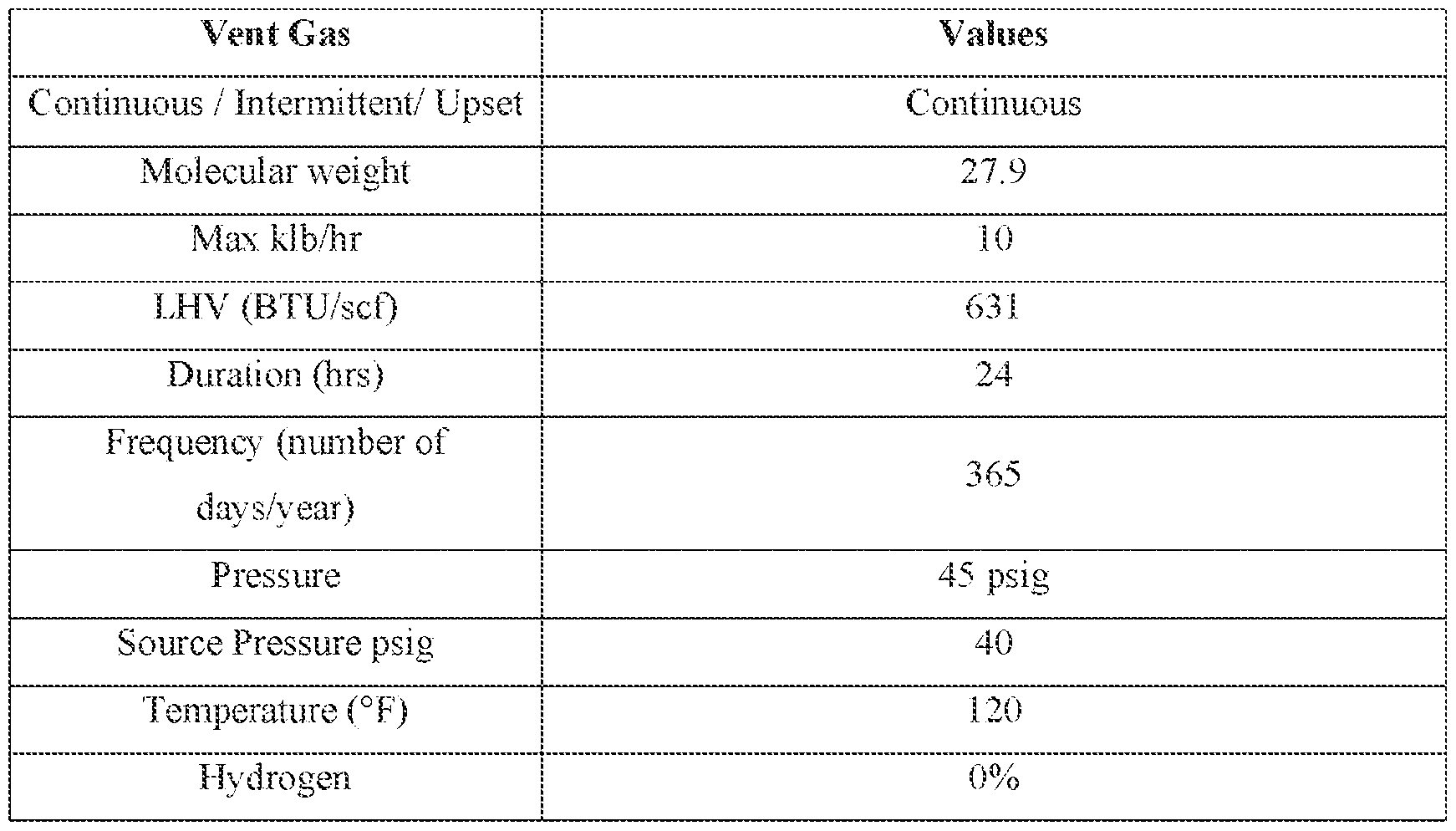
N
2 58% Methane 0%
[0107] Nitrogen existed as the majority gas in the vent stream in the composition of the vent stream. Example 2 [0108] Simulation results when using ethane as the carrier gas in the catalyst feeder as opposed to nitrogen and using fresh ethane gas as the purge gas (also as opposed to nitrogen), were performed, and the results are shown below in Table 2. Table 2. Component Reactor composition (before Reactor composition (after
Butane - - 2,2-dimethylpropane - -
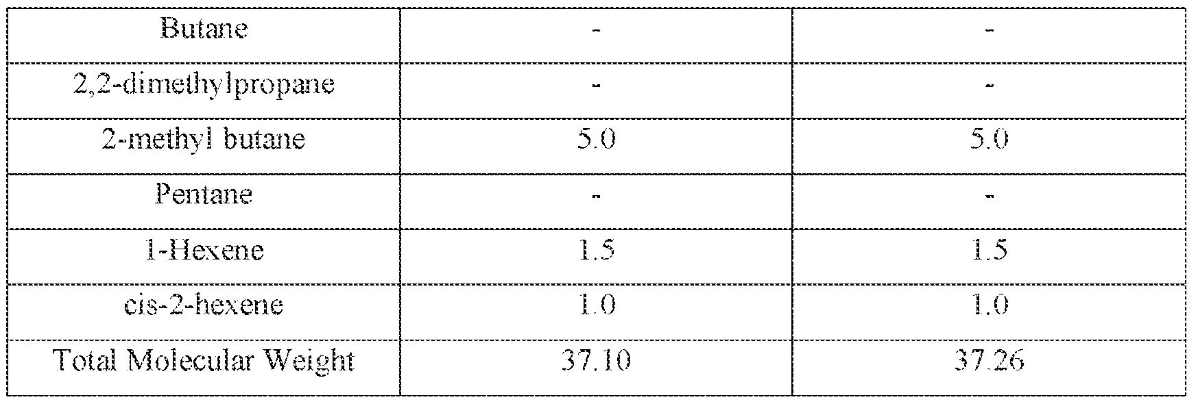
tor gases in the polymerization reactor having a low nitrogen content build up. Moreover, while the nitrogen content decreased, the ethane content increased. Without being bound by theory the decreased nitrogen content and improved ethane content may lead to improved hydrocarbon production and improved hydrocarbon separation in the gas-phase polymerization system 100, and/or can also reduce the need for flaring to prevent excessive build-up of non-participating gases such as nitrogen in the system. Example 3 [0110] An integrated olefins processing plant and polyethylene polymerization system was simulated such that nitrogen was used in the polyethylene polymerization system as the carrier gas in the catalyst feeder and the purge bin was replaced with recycled ethane and/or ethylene. More particularly, a simulation was performed where nitrogen was replaced with nearby- sourced ethane, e.g., ethane obtained and/or recycled from a co-located cracker that might be upstream of any one or more feed lines (e.g., lines 110, 113, 114, 130, 133) to the system 100 of FIG. 1 (not shown in FIGs. 1-3), for use in the catalyst feeder(s) (e.g., via line 113 of FIG. 1) and fresh ethylene from the cracker was used as a purge gas in place of nitrogen. All of the vent stream (100%), half of the vent stream (50%), or none of the vent stream (0%), was simulated being sent to the olefins processing plant or recycled within the polyethylene polymerization system. Where 100% of the vent stream was recycled in the polyethylene polymerization system the nitrogen mol% was reduced from 58 mol% (see Table 1) to 49.2 mol% in the polyethylene polymerization system, as shown below in Table 3. Where 50% of the vent stream was recycled in the polyethylene polymerization system, with the remaining 50% of the vent stream sent to the olefins processing plant, the nitrogen mol% was reduced to 10.5 mol% in the polyethylene polymerization system, as shown below in Table 3. Where 0% of the vent stream was recycled in the polyethylene polymerization system, with 100% of the vent stream being sent to the olefins processing plant, the nitrogen mol% was reduced to 2.8
mol% in the polyethylene polymerization system, as shown below in Table 3, showing a co- located plant that could use the nitrogen may be a viable alternative to flaring or other disposal means, while also preventing nitrogen buildup in the polymerization system. Table 3. Mol% 0% Recycle 50% Recycle 100% Recycle N2 2.8 10.5 49.2
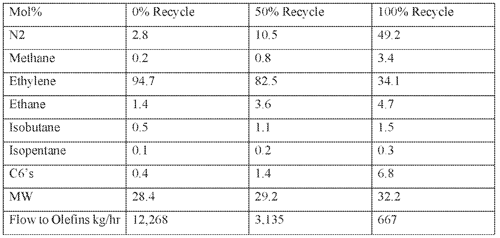
xampe [0111] A production rate comparison of using nitrogen as the carrier gas in the polymerization reactor compared to ethane as the carrier gas in the polymerization reactor was conducted. A 6% increase in polyethylene production occurred by using ethane as the carrier gas in the polymerization reactor as opposed to nitrogen as the carrier gas in the polymerization reactor, as shown in Table 4. Table 4. Nitrogen Ethane Units
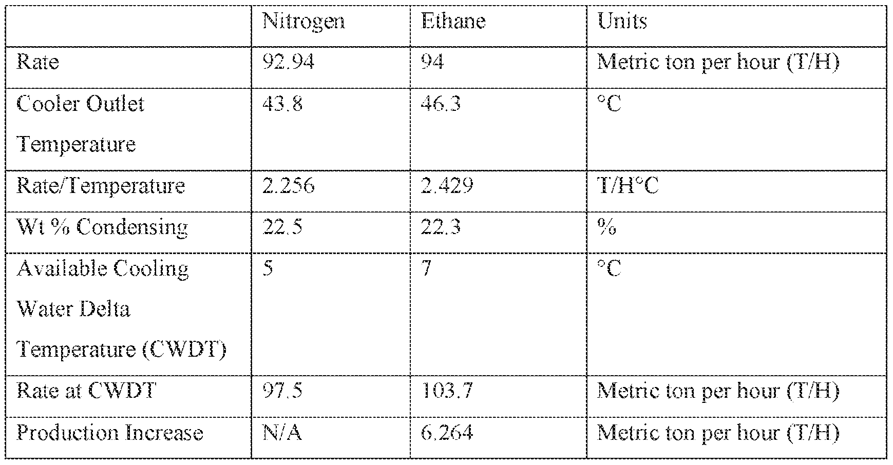
[0112] Overall, a benefit of a production rate increase of the polyethylene product occurred when using ethane gas as the carrier as opposed to nitrogen when operating at the same cooling water temperature. Without being bound by theory, the higher average heat content (heat capacity) of the ethane gas lead to a larger temperature differential between the catalyst or monomer feed line and the top of the reactor, e.g., dome of the reactor, resulting in the 6% increase of polyethylene product production. [0113] Overall, the present disclosure provides processes for improved use of recovery systems of hydrocarbons in gas-phase polymerization processes. The recovery systems provided can utilize a purge gas having a higher heat capacity and/or gas density value such as ethane or ethylene, as compared to nitrogen, to increase the efficiency and production rate of polyolefin products. The present disclosure also provides enhanced hydrocarbon separations downstream of the reactor by substituting ethane gas for nitrogen gas. The present disclosure provides a recovery stream of a reactor of a gas-phase polymerization reaction having a low nitrogen content, e.g., about 1% v/v to about 10% v/v, which allows for the recovery stream to be processed in an olefins plant, e.g., a plant that produces one or more olefins or a plant that polymerizes one or more olefins. The processing of the recovery hydrocarbons may allow for the extraction of one or more hydrocarbons of the recovery stream. The present disclosure also provides use of a carrier gas such as ethane that can match one or more attributes of nitrogen, e.g., temperature or pressure of nitrogen, and be used in conventional areas of nitrogen use to reduce the likelihood of directing hydrocarbons to flaring due to better separation of ethane from hydrocarbons in a purge bin. [0114] The present disclosure provides the use of a mixture of one or more of ethane, or nitrogen with hydrogen and/or water vapor to neutralize one or more catalytic components from further polymerization. The use of hydrogen provides another advantage because hydrogen, when sent to flare downstream, combusts to form water vapor, a more desirable alternative to combustion products of hydrocarbons sent to flare (e.g., CO, CO2). The present disclosure also provides methods of employing heat integration of the carrier gas, such that the temperature of the carrier gas, e.g., ethane, may match the temperature of nitrogen during polymerization reactions, reducing the amount of hydrocarbon compounds sent to flare. The present disclosure also provides a reduction of the use of nitrogen in a purge bin even where nitrogen is typically required to provide a barrier vapor lock in a lower section of the purge bin, e.g., the fourth region of the purge bin, to prevent hydrocarbon leak to the atmosphere, while concurrently reducing undesired flare byproducts emitted to atmosphere by use of hydrogen gas (which combusts to water vapor) in a second purge section of a purge bin.
EMBODIMENTS [0115] The present disclosure provides, among others, the following embodiments, each of which can be considered as optionally including any alternate embodiments: [0116] E1. A method, including recovering a polyolefin product including one or more unreacted components from a polymerization reactor; contacting the polyolefin product with a purge gas to remove at least a portion of the unreacted components to produce (1) a polymer product having a reduced concentration of unreacted components and (2) a purge gas vent stream enriched in unreacted components, wherein the purge gas is selected from the group consisting of hydrogen, methane, ethane, ethylene, and a combination thereof (optionally wherein a portion of the purge gas may also include nitrogen, argon, and/or helium in certain circumstances); directing the purge gas vent stream to a purge gas recovery unit, the purge gas recovery unit configured to cool the purge gas vent stream via a cooler to produce a cooled purge gas vent stream; compress the cooled purge gas vent stream to a pressure of about 60 psi to about 500 psi to form a compressed purge gas vent stream; cool the compressed purge gas vent stream to a temperature of about -30 °C to about 100 °C via a water cooler to form a cooled compressed purge gas vent stream; separate the cooled compressed purge gas vent stream into a gas product and a condensed product; extract the condensed product; and recycle at least a portion of the gas product to be introduced with the purge gas. [0117] E2. The method of embodiment E1, wherein the unreacted components are selected from the group consisting of unreacted monomers, unreacted comonomers, impurities, or catalytic components. [0118] E3. The method of embodiment E2, wherein the purge gas is ethane or ethylene. [0119] E4. The method of any one of embodiments E1-E3, wherein the polymerization reactor is a gas-phase polymerization reactor. [0120] E5. The method of any one of embodiments E1-E4, wherein the purge gas recovery unit is further configured to receive a makeup gas; and introduce the makeup gas to the gas product. [0121] E6. The method of embodiment E5, wherein the makeup gas includes a gas selected from the group consisting of methane, ethane, ethylene, nitrogen, argon, helium, and combinations thereof; alternately wherein the makeup gas does not include nitrogen, argon, and/or helium, but may include any one or more of the other gases just listed. [0122] E7. The method of embodiment E6, wherein the makeup gas is ethane. [0123] E8. The method of embodiment E6, wherein the makeup gas is ethylene.
[0124] E9. The method of any one of embodiments E1-E8, wherein recycling at least a portion of the gas product further includes directing at least a portion of the gas product as purge gas to be introduced with the purge gas to a purge bin; directing at least a portion of the gas product to an olefins processing system; and directing at least a portion of the gas to flare. [0125] E10. The method of any one of embodiments E1-E9, wherein the purge gas recovery unit is further configured to direct at least a remaining portion of the gas product to flare. [0126] E11. The method of any one of embodiments E1-E10, separating the cooled compressed purge gas further includes introducing the cooled compressed purge gas vent stream to a condenser. [0127] E12. A process for recovering unreacted components from a polyolefin purge gas product, the process including: supplying a polymer product of a polymerization reactor to a purge bin, wherein the polymer product includes one or more unreacted components, and wherein the purge bin includes a first region, a second region, a third region, and a fourth region; performing a first strip of the one or more unreacted components from the polymer product by contacting the polymer product in the first region with a first purge gas and recovering at least a portion of the first purge gas as a purge gas vent stream; performing a second strip of the one or more unreacted components from the polymer product by contacting the polymer product in the second region with a second purge gas and directing the second purge gas to flare or a first flare gas recovery unit; performing a third strip of the one or more unreacted components from the polymer product by contacting the polymer product in the third region with a third purge gas to form a stripped polymer product and directing the third purge gas to flare, the first flare gas recovery unit, or a second flare gas recovery unit; directing the stripped polymer product through the fourth region to a rotary feeder to recover the stripped polymer product. The second strip may be performed after the first strip; and the third strip may be performed after the second strip – with respect to a given portion of the polymer product passing through the first, second, and third strip (while recognizing that in a continuous system such as these, the three stripping processes will be occurring simultaneously on different portions of the polymer product as it advances through the regions). [0128] E13. The process of embodiment E12, wherein the one or more unreacted components is selected from the group consisting of an unreacted monomer, an unreacted comonomer, an impurity, a catalytic component, and combinations thereof.
[0129] E14. The process of embodiment E13, further including concurrently neutralizing the one or more catalytic components while performing the second strip of the one or more unreacted components. [0130] E15. The process of embodiment E13, further including concurrently neutralizing the one or more catalytic components while performing the third strip of the one or more unreacted components. [0131] E16. The process of any one of embodiments E12-E15, wherein recovering the first purge gas includes directing the first purge gas to a purge gas recovery unit. [0132] E17. The process of embodiment E16, wherein recovering the second purge gas includes directing the second purge gas to flare or to the first flare gas recovery unit via a first cone. [0133] E18. The process of embodiment E17, wherein recovering the third purge gas includes directing the second purge gas to flare, the first flare gas recovery unit, or to the second flare gas recovery unit via a second cone. [0134] E19. The process of any one of embodiments E12-E18, wherein the first includes a first diameter, the second region includes a second diameter, the third region includes a third diameter, and the fourth region includes a fourth diameter. [0135] E20. The process of claim E19, wherein the first diameter is larger than the second diameter, the second diameter is larger than the third diameter, and the third diameter is larger than the fourth diameter. [0136] E21. The process of any one of embodiments E12-E20, wherein the first gas is selected from the group consisting of hydrogen, water vapor, methane, ethane, ethylene, argon, helium, and combinations thereof, alternately wherein the first gas does not include argon or helium but can include any one or more of the other gases just listed. [0137] E22. The process of embodiment E21, wherein the first gas is ethane. [0138] E23. The process of any one of embodiments E12-E22, wherein the second gas is selected from the group consisting of hydrogen, water vapor, methane, ethane, ethylene, argon, helium, and combinations thereof, alternately wherein the second gas does not include argon or helium but can include any one or more of the other gases just listed. [0139] E24. The process of embodiment E23, wherein the second gas is ethane and/or hydrogen. [0140] E25. The process of any one of embodiments E12-E24, wherein the third gas is selected from the group consisting of hydrogen, water vapor, methane, ethane, ethylene, argon, helium, nitrogen, and combinations thereof.
[0141] E26. The process of embodiment E25, wherein the third gas is nitrogen and/or water vapor. [0142] E27. A method including introducing an ethylene monomer to a polymerization reactor; introducing a catalyst to the polymerization reactor using a catalyst feed, wherein the catalyst is introduced using a carrier gas; polymerizing the ethylene monomer in the presence of the catalyst to yield a polymer product and an unreacted components stream; separating the polymer product from the unreacted components stream to form a polymer product and a purge gas vent stream, the purge gas vent stream including the one or more unreacted components; recovering the polymer product; and recycling the purge gas vent stream to be introduced with the catalyst to the polymerization reactor. [0143] E28. The method of embodiment E27, wherein the unreacted components are selected from the group consisting of unreacted monomers, unreacted comonomers, impurities, or catalytic components. [0144] E29. The method of embodiment E27 or E28, wherein the carrier gas is selected from the group consisting of methane, ethane, ethylene, nitrogen, argon, and helium; alternately wherein the carrier gas does not include nitrogen, argon, and/or helium, but may include any one or more of the other just-listed gases. [0145] E30. The method of embodiment E29, wherein the carrier gas is ethane. [0146] E31. The method of embodiment E29, wherein the carrier gas is ethylene. [0147] E32. The method of any one of embodiments E27-E31, wherein the carrier gas comprises about 20% v/v to about 100% v/v of ethylene and about 0% v/v to about 80% v/v ethane, wherein a total % of the carrier gas does not exceed 100% v/v. [0148] E33. The method of any one of embodiments E27-E32, wherein the carrier gas includes the recycled purge gas vent stream. [0149] E34. A method including: introducing an ethylene monomer to a polymerization reactor; introducing a catalyst to the polymerization reactor using a catalyst feed, wherein the catalyst is introduced using a carrier gas; polymerizing the ethylene monomer in the presence of the catalyst to yield a first polymer product and an unreacted components stream; separating the polymer product from the unreacted components stream using a purge gas to form a second polymer product and a purge gas vent stream, the purge gas vent stream including the one or more unreacted components; recovering the second polymer product; and recycling the purge gas vent stream to be introduced with the catalyst to the polymerization reactor, wherein recycling the purge gas vent stream further includes: introducing the purge gas vent stream to a purge gas recovery unit configured to: cool the purge gas vent stream via
a cooler to form a cooled purged gas vent stream; compress the cooled purged gas vent stream to a pressure of about 60 psi to about 500 psi to form a compressed purge gas vent stream; cool the compressed purge gas vent stream to a temperature of about 0.1 °C to about 100 °C via a water cooler to form a cooled compressed purge gas vent stream; separate the cooled compressed purge gas vent stream into a gas product and a condensed product; extract the condensed product; and recycle at least a portion of the gas product to be introduced as the purge gas. [0150] E35. The method of embodiment E34, wherein the carrier gas is selected from the group consisting of methane, ethane, ethylene, nitrogen, argon, helium, and combinations thereof; alternately wherein the carrier gas does not include nitrogen but may include any one or more of the other just-listed gases. [0151] E36. The method of embodiment E35, wherein the carrier gas is ethane. The method of embodiment E35, wherein the carrier gas is ethylene. The method of any one of embodiments E34-E37, wherein the carrier about 20% v/v to about 100% v/v of ethylene and about 0% v/v to about 80%
v/v ethane, wherein a total % of carrier gas does not exceed 100% v/v. [0154] E39. The method of any one of embodiments E34-E38, wherein the carrier gas includes the recycled purge gas vent stream. [0155] E40. The method of any one of embodiments E34-E39, wherein the purge gas recovery unit is further configured to receive a makeup gas; and introduce the makeup gas to the gas product. [0156] E41. The method of any one of embodiments E34-E40, wherein the purge gas recovery unit is further configured to direct at least a portion of the gas product to be introduced with the purge gas; direct at least a portion of the gas product to an olefins processing system; and direct at least a portion of the gas product to flare. [0157] E42. The method of any one of embodiments E34-E41, wherein the purge gas recovery unit is further configured to direct at least a remaining portion of the gas product to flare. [0158] E43. The method of any one of embodiments E34-E42, wherein the purge gas recovery unit is further configured to introduce the cooled compressed purge gas vent stream to a condenser. [0159] E44. A method including introducing an ethylene monomer to a polymerization reactor; introducing a catalyst to the polymerization reactor using a catalyst feed, wherein the catalyst is introduced using a carrier gas; polymerizing the ethylene monomer
in the presence of the catalyst to yield a polymer product and an unreacted components stream; separating the polymer product from the unreacted components stream to form a polymer product and a purge gas vent stream, wherein separating the polymer product from the unreacted components further includes: supplying the polymer product to a purge bin, wherein the purge bin includes a first region, a second region, a third region, and a fourth region; performing a first strip of the one or more unreacted components from the polymer product by contacting the polymer product in the first region with a first purge gas and recovering the first purge gas as the purge gas vent stream; performing a second strip of the one or more unreacted components from the polymer product by contacting the polymer product in the second region with a second purge gas and directing the second purge gas to flare or a first flare gas recovery unit; performing a third strip of the one or more unreacted components from the polymer product by contacting the polymer product in the third region with a third purge gas to form a stripped polymer product and directing the third purge gas to flare, the first flare gas recovery unit, or a second flare gas recovery unit; and directing the third stripped polymer product through the fourth region to a rotary feeder to recover the third stripped polymer product. [0160] E45. The method of embodiment E34, wherein the carrier gas includes ethane, ethylene, or a combination thereof. [0161] E46. The method of embodiment E38 or E39, further including recycling the purge gas vent stream by directing the purge gas vent stream to a purge gas recovery unit. [0162] Certain embodiments and features have been described using a set of numerical upper limits and a set of numerical lower limits. It should be appreciated that ranges including the combination of any two values, e.g., the combination of any lower value with any upper value, the combination of any two lower values, and/or the combination of any two upper values are contemplated unless otherwise indicated. Certain lower limits, upper limits and ranges appear in one or more claims below. All numerical values are "about" or "approximately" the indicated value, and take into account experimental error and variations that would be expected by a person having ordinary skill in the art. [0163] All priority documents are herein fully incorporated by reference for all purposes and for all jurisdictions in which such incorporation is permitted and to the extent such description is consistent with the present disclosure. Further, all documents and references cited herein, including testing procedures, publications, patents, journal articles, etc. are herein fully incorporated by reference for all jurisdictions in which such incorporation is permitted and to the extent such description is consistent with the disclosure.
[0164] Likewise, whenever a composition, an element or a group of elements is preceded with the transitional phrase “comprising”, it is understood that we also contemplate the same composition or group of elements with transitional phrases “consisting essentially of,” “consisting of”, “selected from the group of consisting of,” or “is” preceding the recitation of the composition, element, or elements and vice versa. The phrases, unless otherwise specified, “consists essentially of” and “consisting essentially of” do not exclude the presence of other steps, elements, or materials, whether or not, specifically mentioned in this specification, so long as such steps, elements, or materials, do not affect the basic and novel characteristics of the claimed disclosure, additionally, the phrases do not exclude impurities and variances normally associated with the elements and materials used. [0165] While the claimed disclosure is described with respect to a number of embodiments and examples, those skilled in the art, having benefit of this disclosure, will appreciate that other embodiments can be devised which do not depart from the scope and spirit of the disclosure.
 [0107] Nitrogen existed as the majority gas in the vent stream in the composition of the vent stream. Example 2 [0108] Simulation results when using ethane as the carrier gas in the catalyst feeder as opposed to nitrogen and using fresh ethane gas as the purge gas (also as opposed to nitrogen), were performed, and the results are shown below in Table 2. Table 2. Component Reactor composition (before Reactor composition (after
 Butane - - 2,2-dimethylpropane - -